
Section 3: Creating a 2D Model with DeepEX
- Feb 13, 2024
- 39 min read
Updated: May 20, 2025
SECTION 3: CREATING A 2D MODEL WITH DEEPEX
DeepEX can turn the underground project design into a game. Any model can be created graphically on the model area and all parameters can be defined and modified in the most comprehensive way. The DeepEX drawing tools can create any model in minutes and the software properties estimation tools can help us get started working in any model.
This section presents how to create any deep excavation model in DeepEX graphically. We present how to define the model general elevation and dimensions, how to edit the soil properties, creating the list of soils we wish to use in a specific project and how to edit and define the boreholes (borings – stratigraphy). We present the options to edit the ground surface and the custom layer mode that allows us to define non-horizontal stratigraphy or change the soil properties on the one wall side (in case of a backfill with a different material or use of jet grout) – properties that can be edited also with the soil change commands of DeepEX. We present how to define lists of structural sections for all wall and support types and how to graphically add supports and external load to the model area in order to edit and create each construction stage. Finally, we provide information on external loads that can be used in DeepEX, and how to define the method for the transfer of the external loads horizontally on the wall.
In DeepEX, we can define the actual model surface elevation. All the current items elevation coordinates (ground surface and soil layer points, water table, support locations etc.) will change according to this selection.

Figure 3.1.1: Edit general elevation options
Our general recommendation is to always use actual elevations for project design, and define the general elevation in the beginning, before any other operation. |
The option “All Boreholes (Layers) in the dialog is by default unselected. This is to avoid changing the reference elevation in or boreholes (if more than one borings are created in the project file), and keep the change effect in the boring that is currently selected. We can of course choose to pass the change to all borings at the same tie if needed. The same applies to the Footings and Buildings elevations (if they are currently installed before the general elevation change).
Also in the General tab of the software, we can select the option Move model Dim-Limits. In the dialog that appears (Figure 3.1.2) we can define the design section name, the model boundaries (top, bottom, left and right), change the angle in plane of the y-y’ axis (the default value is 0), and choose the excavation shape (2D, Box type, Circular shaft, Corner).
The Out of Plane y-y’ will affect the Top View, which can be accessed from the View tab of DeepEX (Figure 3.1.3).

Figure 3.1.2: Design section options and limits

Figure 3.1.3: Top view – wall rotated 20 deg from y-y’ axis
One of the first actions to create a project in DeepEX software is to review the geotechnical report and create a list of soils with their soil properties. These soils can be later used to define the actual stratigraphy of the project area.
By pressing the Edit soil type data button of the General tab of DeepEX, the Soil Types dialog appears. Here the we can use the options on the left side of the dialog to create as many soil types as needed (Figure 3.2.1), access them one by one and define their properties.

Figure 3.2.1: Open soil types dialog and edit list of soils

Figure 3.2.2: Define name, color and soil type of each soil
Depending on the soil type of each soil (Sand, Clay, Silt, Gravel, Intermediate geo-material or Rock), we have to define the general soil properties. Several properties can be defined for each soil (Poisson’s ratio, permeability, At-rest Earth Coefficients etc.). For frictional soils (sands, silts, etc.) we have to define the unit weights, the cohesion and the friction angle (Figure 3.2.3). For clays, we also have to define the default clay behavior (drained or undrained). Based on this selection, we have either to define the drained shear strength of the clay and the friction angle (drained condition), or the undrained shear strength of the clay Su. In addition, for clays, we can define the minimum pressures (the default value in DeepEX is 0).
Our general recommendation is to review the geotechnical report carefully and always consult the person who conducted the report about the proper soil types and properties. The use of undrained clay behavior should be avoided for clays that are located above the water table, since it is unlikely to be fully saturated, thus working as an undrained clay. |

Figure 3.2.3: General soil properties – Sands and Clays
When an advanced analysis method is used (Non-Linear or Finite Element analysis), then the options in the tab Elasto-plastic are available (Figure 3.2.4). In this tab we can select the soil model of each soil (elastoplastic, exponential, subgrade-modulus, small strain hardening), and accordingly define the soil properties of the soil (modulus of Elasticity, exponent, subgrade reaction modulus, small strain parameters etc.). The reloading elasticity parameter of the soil is usually defined as 3 times (or more) greater than the loading modulus.
NOTE: The options on this tab are not available when Limit Equilibrium method is selected. |

Figure 3.2.4: Soil model options (Exponential and Small Strain Hardening)
When we have tiebacks or soil nails bonded in any of the soils, we have to access the Bond tab and define the ultimate bond resistance for tiebacks and soil nails (Figure 3.2.5). The bond resistance is the skin friction and is used in the calculation of the geotechnical pullout capacity of the tiebacks or soil nails. In the same tab we can define the subgrade reaction modulus for soil nails and the ultimate bond resistance for concrete walls.
When we use the pile supported abutment module of DeepEX (optional additional module), we have to access the Piles tab, where we can define the lateral pressure parameters of each soil (subgrade reaction modulus for sands, e50 value for clays, Krm value for rocks). These properties are used for the lateral analysis of the supporting foundation piles that can be applied with this module.

Figure 3.2.5: Bond resistances and lateral pile analysis options
The soil properties in DeepEX can be defined using the following methods:
A. Manually defined by the user based on the geotechnical report, previous projects and the designer experience.
B. Use of the DeepEX SPT Estimator tool. When we press the Show test data button, we can access the DeepEX SPT Estimator., where we can define the NSPT value for the specific soil in the NSPT bar. The software can estimate the soil properties from the NSPT. Choosing the option “Elasticity modulus”, the elasticity parameters of the soil can also be estimated.

Figure 3.2.6: SPT Estimator in DeepEX
C. Use of the partial estimation tools, existing next to almost every value (small arrows). Some of these arrows will offer specific values based on soil types, and some others will propose scientific methods for the calculation of the specific value. In this case, we will have to define one on more test results in the Test Data tab (data for standard penetration tests, cone penetrometer tests, pressuremeter tests etc.).

Figure 3.2.7: Local soil property estimation tools in DeepEX
Finally, after we create the soils and define the soil properties, we can choose the option at the bottom of this dialog in order to save the soil in a pc folder. We could press the button open from database and load the saved soil in different DeepEX project files, saving time in case we need to design a project in the same area, or if according to the geotechnical report we have to use soils with similar soil properties.
In case we need to change the soil properties within construction stages or use different soil properties on the two wall sides (i.e. when we backfill with a different soil), we can use the DeepEX Soil Change Commands option, to simulate these changes.
We can choose to add a soil change commands, select the soil and the property and define the new property value. Unlimited number of soil change commands can be used in any construction stage, to simulate all needed soil property changes.

Figure 3.3.1: Soil change commands in DeepEX

Figure 3.3.2: Resisting side soil properties edited with soil change commands
In any DeepEX project file we can define unlimited number of borings, to simulate all different boreholes as described in the geotechnical report. If needed, we can assign a different boring in each design section from the drop-down in the General tab of DeepEX.

Figure 3.4.1: Assign a boring to the selected design section
When we select the option Edit Boring in the General tab of DeepEX, the Edit Soil Layers dialog appears. There we can select to add new borings in the project database. We can access each one of them and define the stratigraphy by defining top of the soil layer elevation and select a soil type below the specified elevation from the list of soils, for each soil layer (Figure 3.4.2). We can repeat soil types in different depths.
In the same dialog, we can also choose to add and assign an SPT (Figure 3.4.3) or CPT (Figure 3.4.4) records. CPT records can be added using excel files. In case we define a record, DeepEX will use the soil types of the soil layers we defined and will estimate the soil properties from the records. Figure 3.4.5 presents the SPT and CPT Estimation options.

Figure 3.4.2: Define soil layers in DeepEX

Figure 3.4.3: Add and define an SPT record in DeepEX

Figure 3.4.4: Add and define a CPT record in DeepEX

Figure 3.4.5: SPT and CPT properties estimation options
In DeepEX software the local x-axis in each design section is along the screen. The x-coordinate 0 is by default the top left point of the main (left) wall. There are several ways to edit the ground surface in order to simulate the exact project surface.
Our general recommendation is that the points should keep their order from left to right along the x-axis. Please do not define for a point and x-coordinate that is smaller than the one of the closest left point, or bigger than the one of the closest right point. |
Edit the surface points manually
Along the main surface on the interactive model area there are surface points, which we can access (double-click on them) and define the x-coordinate and elevation of each point.

Figure 3.5.1: Edit a surface point manually
Edit the surface points using the table of coordinates tool
In the General tab of DeepEX, under the Surface Options selection, we can choose to edit the table of coordinates. This option loads the table, in which we can locate all existing surface points, we can edit the X-coordinate and elevation of each point and we can choose to add new surface points (a new point is added right before the point we have selected before pressing to add a new one). This way, we can add several points and simulate a more composite ground surface.
Our general recommendation is not to change from the table the points representing the top left and right point of each wall. These points are automatically adjusted when we move the wall from the Edit Wall dialog (when we double-click on the wall) and when we define the wall structural section, thus the wall thickness. |

Figure 3.5.2: Option to load surface points Table of Coordinates

Figure 3.5.3: Surface points edited with the Table of Coordinates tool
Create Slope or Bench Surfaces Automatically
DeepEX includes tools that allow us to create slope or bench surfaces on the left or right side of each wall automatically. These tools can be accessed either from the Surface Options selection in the General tab of the software (Figure 3.5.2), or by right-clicking with the mouse on the model area close to the surface that we wish to edit (Figure 3.5.4).
In the dialog that appears when a tool is selected, we can select and define the surface or bench properties (slope angle, bench offset, bench elevation etc.).

Figure 3.5.4: Automatic surface options

Figure 3.5.5: Left bench surface in DeepEX
NOTE: Any surface modification will take effect only in the selected construction stage. The change will pass automatically to the following stages ONLY if the stages are generated after the modification. |
DeepEX includes a Custom Layer mode that can generate lines with points, simulating the surface of each soil layer. This way, we can define non-horizontal stratigraphies below the ground surface. The Custom Layer options are included in the General tab of DeepEX (Figure 3.6.1).
Our general recommendation is to always define all soil layers horizontally using the Borings dialog (see section 3.4), and then choose to generate the custom layers. |

Figure 3.6.1: Custom layer options in DeepEX
Generating custom layers
In order to create the custom layers for the first time in a specific project file, we have to access the Custom Layers options in the General tab of DeepEX (Figure 3.6.1), select the option “Use custom layers”, access again and select the option “Reset layers from boring”. This action will generate new lines with points simulating the surface line of each soil layer of the boring we have currently selected (Figure 3.6.2).
After the first time the soil layers are generated, the “Use custom layers” option can be used as a toggle button to change between normal and custom layer mode of DeepEX. The “Reset layers from boring” option can be used to generate again the custom layers using the same or a different boring (depending on the selected boring in the specific design section).

Figure 3.6.2: Custom layer lines generated in DeepEX
Editing custom layers
When the Custom Layer mode is on, we can access the soil layer lines with our mouse. The lines will highlight, allowing us to double-click on them and edit their properties. In the dialog that appears we can define the position (x-coordinate and elevation) of each layer point, select to add new points and even change the soil type below the selected custom layer line. The same dialog can be accessed when we press right on the Custom Layers button in the general tab of DeepEX (not on the arrow). There we can select which layer we wish to edit.

Figure 3.6.3: Edit a custom layer in DeepEX
Drawing a new custom layer
When the DeepEX Custom Layer mode is on, we can select the option “Draw a layer line (see Figure 3.6.1). By selecting this tool, we can click on the model area on several points (from left to right along the screen). By pressing “Enter” from the keyboard, the new soil layer line is generated and we can define the exact coordinates of all line points and the soil type below the new layer line.

Figure 3.6.4: Draw and edit a new custom layer
Changing the view order of custom layers
When the Custom Layer mode is on, the soil layer properties are presented in Table format. The order of the soil layers from top to bottom in this table is significant, as layers closer to the bottom of the table are closer to the viewer. We can change the order by right-clicking on any layer line on the model area and select to “Bring to Front” or “Send to Back”.

Figure 3.6.5: Change the order of custom layers
In DeepEX we can create unlimited number of wall sections, define the section properties and assign easily different sections to different walls. The Wall sections dialog can be accessed either from the Edit Wall dialog (which appears when we double-click on the wall – see section 3.18), or by the General tab of DeepEX (Figure 3.7.1).

Figure 3.7.1: Option to edit wall sections in DeepEX General tab
In the “Edit wall sections” dialog (Figure 3.7.2), we can select to create several new wall sections in the list or the left. These sections can be accessed and modified independently. For each wall section we can define the section name, wall type and based on the wall type the wall section properties (dimensions, reinforcement etc.).

Figure 3.7.2: Edit wall sections dialog – create new sections
Our general recommendation is to create a new independent wall section for each wall in the project. A created wall section can be assigned to multiple walls in the same or different design sections. Nevertheless, it is recommended to create new sections, even if they are identical, so they can be easily and independently optimized manually, or with the software optimization tools. |
Selecting a wall type
For each wall section, we have to define the wall type. DeepEX includes an extensive list of wall types that can be selected by pressing on buttons. Any selected option will deactivate all other wall type parameters. The following tables present the software selections for each wall type.
Table 3.7.3: Soldier pile and lagging wall types

Table 3.7.4: Sheet and Secant pile wall types

Table 3.7.5: Tangent piles and Diaphragm walls

Table 3.7.6: SPTC, Combined sheet piles, Box sheet piles and custom walls

Defining Reinforced Concrete Properties
When we select to use any reinforced concrete wall type (reinforced concrete piles, Diaphragms), the Concrete-Rebar tab appears. In this tab we can define the pile diameter (or the diaphragm thickness and panel width), the number, size and concrete cover of longitudinal reinforcement and the size/spacing of the shear reinforcement.

Figure 3.7.7: Define reinforced concrete section properties
In this tab we can also select the option “Define custom reinforcement”. This selection will disable the automatic longitudinal reinforcement options, and we can select to draw on the concrete section and define the exact position and size of each rebar.

Figure 3.7.8: Define custom rebar reinforcement
Defining Steel Sections
DeepEX implements extensive international databases of steel sections (H beams, Pipes, Channel sections, Rectangular hollow sections, sheet piles, box sheet piles, combined sections). When a steel supported wall type is selected, we can access the Steel Beams (or Sheet piles) tab, where we can select a section from the lists. The section properties are implemented in the software and loaded automatically. We have the option to manually edit the properties in order to simulate any steel section we might not include.

Figure 3.7.9: Select an H Beam section from database
In case of pipes, apart from the software database, we can also type the required PP or metric pipe section in the section box using the PP or PM respectively, followed by the pipe diameter in inches or mm, then the symbol X and finally the pipe diameter (inches or mm) and press “Enter”. The software calculates the section properties directly. In example, to use a metric pipe with 50cm diameter and 2 cm thickness we should type PM500X20 and press “Enter”.

Figure 3.7.10: Define pipe section manually
Defining Spacing and Pressure Widths below Excavation
In the tab A. Wall Type, apart from choosing the wall section type, we can also define the wall spacing and the widths for the calculation of active, water and passive pressures.
For pile walls (like soldier piles, tangent piles etc.) the Spacing represents the distance between each supporting pile (center to center). For continuous walls (like SPTC, sheet piles and diaphragms) the spacing represents the effective width of the examined wall.
Our general recommendation for continuous walls is to use as spacing S=1ft or S=1m so the software calculates and presents the results per ft or per m of the examined wall.
For continuous walls, it is recommended to use the wall spacing as widths for the calculation of active, passive and water pressures below excavation.

Figure 3.7.11: Define spacing and pressure widths for continuous walls
For soldier pile and lagging walls (or combined sheet pile walls) where there is no presence of lagging below the excavation, it is recommended to use the pile diameter or flange size as width for the calculation of active and water pressures, and 2.5 to 3 times this width for the calculation of passive pressures. The widths are limited by the wall spacing (Figure 3.7.12).
When we use steel section soldier piles, the pile width d is automatically defined by the software, using the maximum steel section dimension (flange, web). These are supposed to be steel piles driven into the soil. In case we wish to use steel sections installed in drilled holes and covered with concrete, we should just increase the pile width d manually, defining the pile hole diameter (Figure 3.7.13).

Figure 3.7.12: Define spacing and pressure widths for soldier pile walls

Figure 3.7.13: Driven and drilled soldier piles
Defining Lagging Type, Thickness and Position
The Lagging tab appears when any Soldier pile and lagging wall section is selected. In this tab we can select the lagging type (timber, concrete or steel plate), the lagging structural section and material, as well as the lagging position and calculation method. In case of timber or steel plate lagging, we have to define the lagging thickness (Figure 3.7.14). In case of concrete lagging, we can edit the structural section, defining lagging thickness and rebar reinforcement (Figure 3.7.15).

Figure 3.7.14: Define lagging properties in DeepEX

Figure 3.7.15: Define concrete lagging section properties
In DeepEX we can create unlimited number of ground anchor (tieback) sections, define the section properties and assign easily different sections to different tieback supports. The Tieback Anchors sections dialog can be accessed either from the Edit Support dialog (which appears when we add a new support or double-click on an existing support – see section 3.22), or by the General tab of DeepEX (Figure 3.8.1).

Figure 3.8.1: Option to define tieback sections in DeepEX General tab
In the Tieback Anchors sections dialog we can create a list of tieback sections. We can access each tieback section independently and modify it, defining the tieback structural section type, the material and dimensions, the grout options and a geotechnical factor of safety.
Our general recommendation is to create a new independent tieback section for each ground anchor in the project. A created tieback section can be assigned to multiple tiebacks in the same or different design sections. Nevertheless, it is recommended to create new sections, even if they are identical, so they can be easily and independently optimized manually, or with the software optimization tools. |
Defining Tieback Section Type and Structural Properties
The tieback structural section for each created tieback can be selected from five main types:
A) Strands or user bars
B) Solid bar
C) User area
D) Pipe micropile
E) Beam micropile
Depending on the selected type, we can define the material, the structural sections (strand or solid bars diameter and number, pipe or H Beam size etc.) and the grout options (diameter and material).

Figure 3.8.2: Define new tieback sections and edit type and structural properties
Defining Geotechnical Safety Factor and Properties
The geotechnical safety factor in this dialog is used when the custom Geo FS and/or the Use bond values to calculate geotechnical capacity options are not selected in the Design tab of the main program. In most cases, tiebacks are pressure grouted in order to achieve greater capacities. We can capture such effects by including a densification multiplier for the frictional and cohesional components of the shear resistance. For the cohesional component you can select an adhesion factor behavior (multiplier for the cohesion). The frictional component of the tieback capacity is calculated from the average effective confining stress at the tieback (at-rest on sides + vertical on top & bottom). Bearing capacity is ignored.
NOTE: The densification factors require careful consideration and can be used to obtain a preliminary estimate of geotechnical tieback capacity. In the overwhelming majority of projects, all tiebacks have to be tested. |

Figure 3.8.3: Define tieback geotechnical safety factor and properties
Defining Custom Structural Capacities
In the Advanced tab of this dialog, we can review and edit the structural capacities of tiebacks and sectional propertied of soil nails. These properties are automatically calculated based on the defined anchor material and structural section and can be manually edited by the user. Also, in this dialog we can define an allowable stress factor for each tieback, which will be used when the option “Default options from tieback” is selected in the Design tab of the main program.

Figure 3.8.4: Custom tieback and soil nail section capacities

Figure 3.8.5: Allowable stress factors for tiebacks
In DeepEX we can create unlimited number of strut (and raker) sections, define the section properties and assign easily different sections to different strut or raker supports. The Strut sections dialog can be accessed either from the Edit Support dialog (which appears when we add a new support or double-click on an existing support – see section 3.22), or by the General tab of DeepEX (Figure 3.9.1).

Figure 3.9.1: Option to define strut sections in DeepEX General tab
In the Strut sections dialog we can create a list of strut sections. We can access each strut section independently and modify it, defining the strut structural section type, the material and the strut steel section size.
Our general recommendation is to create a new independent strut section for each strut and raker in the project. A created strut section can be assigned to multiple supports in the same or different design sections. Nevertheless, it is recommended to create new sections, even if they are identical, so they can be easily and independently optimized manually, or with the software optimization tools. |
Defining Strut Section Type and Structural Properties
In the Strut sections dialog we can select the beam type (H Beam, Pipe, or Rectangular hollow section), and based on this selection we can choose a steel member structural section from the DeepEX international implemented databases. The section properties are implemented in the software and can be accessed and modified manually if we need to simulate a section that is not included in DeepEX.
In this dialog we can also define the material, the section orientation for H beams (flat or vertical), as well as, the number of steel members (if we wish to use double members).

Figure 3.9.2: Add and define strut and raker sections
In DeepEX we can create unlimited number of mechanical and hydraulic strut sections, define the section properties and assign easily different sections to different strut or raker supports. The Mechanical and Hydraulic Strut sections dialog can be accessed either from the Edit Support dialog (which appears when we add a new support or double-click on an existing support – see section 3.22), or by the General tab of DeepEX (Figure 3.10.1).

Figure 3.10.1: Option to define mechanical/hydraulic strut sections in DeepEX General tab
In the Mechanical and Hydraulic Strut sections dialog we can create a list of sections. We can access each strut section independently and modify it, defining the strut structural section type, the material, the strut steel section size and the hydraulic jack properties.
Apart from the structural section, we can also define the axial capacity (usually provided by the manufacturer, the transition unit sections and the connector plates. Finally, we can define standard lengths of units (also provided by the manufacturer).
Our general recommendation is to create a new independent strut section for each strut and raker in the project. A created strut section can be assigned to multiple supports in the same or different design sections. Nevertheless, it is recommended to create new sections, even if they are identical, so they can be easily and independently optimized manually, or with the software optimization tools. |
Defining Strut Section and Hydraulic Jack Properties
Mechanical and Hydraulic struts and rakers in DeepEX can be either hollow square sections, or pipes. We can choose a steel member structural section from the DeepEX international implemented databases. Apart from the main strut section, we can also define the hydraulic unit and piston dimensions and properties, as well as, the start connector length. The hydraulic unit properties should be defined by the manufacturer.

Figure 3.10.2: Define mechanical and hydraulic strut section and jack properties
Defining strut axial capacity
In DeepEX we can define allowable and ultimate axial capacity curves for each created mechanical or hydraulic strut section (usually provided by the manufacturer). In the Strength tab we can select to add envelope and define the lengths by defining length and axial capacity. Also, we can select it the capacity profile if factored (allowable), or ultimate.

Figure 3.10.3: Define mechanical and hydraulic strut axial capacity envelopes
Alternatively, we can specify an exact allowable and max capacity that can be used as cutoff values in stress checks.

Figure 3.10.4: Define mechanical and hydraulic strut rated strengths
Defining transition units
In the C. Transition Units tab we can select to add transition units at the 2 ends of the strut. We need to define the transition unit length, and then the option to edit the unit will be available. In the new dialog we can set the length of the unit, the unit type (pipe or rectangular hollow section), the diameter or size of the start and the end of the unit and the unit thickness. We can also define the thickness and diameter of the connection flanges. Finally, if needed, we can select to use stiffeners and define the stiffener parameters.

Figure 3.10.5: Option to use and edit a transition unit

Figure 3.10.6: Hydraulic unit, transition unit and connecting flanges in DeepEX
Defining transition units
In the D. Connector plates tab we can select the start and end connector type (pin type or base plate) and the dimensions of the connection plates at connections and at the strut (if existing).

Figure 3.10.7: Connector plates options in DeepEX
Defining transition units
In the E. Standard Lengths tab, we can define some standard lengths that can be used by the software Autocomplete tool, to generate the strut on the 3D model automatically (3D Frame Analysis additional optional module required).

Figure 3.10.8: Standard lengths for mechanical and hydraulic struts in DeepEX
In DeepEX we can create and use helical anchor sections instead of normal tieback supports. The Tieback Anchors sections dialog can be accessed either from the Edit Support dialog (which appears when we add a new tieback support or double-click on an existing support – see section 3.22), or by the General tab of DeepEX (Figure 3.11.1).

Figure 3.11.1: Option to define helical anchor sections in DeepEX General tab
In the Helical Anchors sections dialog we can create a list of tieback sections. We can access each tieback section independently and modify it, defining the anchor structural section type, the material and dimensions, the helix configurations and the parameters for the geotechnical capacity calculations.
Our general recommendation is to create a new independent section for each helical anchor in the project. A created helical anchor section can be assigned to tiebacks in the same or different design sections. Nevertheless, it is recommended to create new sections, even if they are identical, so they can be easily and independently optimized manually, or with the software optimization tools. |
In the Helical Anchors dialog we can select an anchor from the existing database of anchors or add some sections to the database. All the created anchors can be accessed and modified independently. In the General tab, we can define the pipe diameter, thickness and material, the torsional pipe capacity and the helix configuration (number of helixes, diameter and thickness of each helix, helix spacing).

Figure 3.11.2: Define helical anchor section properties
In the Geotechnical capacity options tab, we can select and define the parameters for the pullout capacity method.

Figure 3.11.3: Helical anchor geotechnical capacity options
In DeepEX we can create unlimited number of reinforced concrete slab sections, define the section properties and assign easily different sections to different slab supports. The Slab sections dialog can be accessed either from the Edit Support dialog (which appears when we add a new support or double-click on an existing support – see section 3.22), or by the General tab of DeepEX (Figure 3.12.1).

Figure 3.12.1: Option to define strut sections in DeepEX General tab
Our general recommendation is to create a new independent slab section for each slab in the project. A created slab section can be assigned to multiple supports in the same or different design sections. Nevertheless, it is recommended to create new sections, even if they are identical, so they can be easily and independently optimized manually, or with the software optimization tools. |
Defining Slab Section Structural Properties
In the Slab sections dialog we can define the slab thickness, materials and the longitudinal and shear reinforcement (number/size of rebars or rebar spacing).

Figure 3.12.2: Add and define slab sections
In DeepEX the walers can be used either as waler beams that can be added on any already created support (tiebacks, struts, rakers, concrete slabs), or as standalone wale supports. we can create unlimited number of waler sections, define the section properties and assign easily different sections to different walers. The Waler and Hydraulic Waler sections dialogs can be accessed either from the Edit Support dialog (which appears when we add a new waler or double-click on an existing waler – see sections 3.14 and 3.23), or by the General tab of DeepEX (Figure 3.13.1).

Figure 3.13.1: Option to define waler and hydraulic waler sections in DeepEX General tab
Our general recommendation is to create a new independent wale section for each waler in the project. A created wale section can be assigned to multiple waler beams and waler supports in the same or different design sections. Nevertheless, it is recommended to create new sections, even if they are identical, so they can be easily and independently optimized. |
Defining Steel Section Waler Beam Properties
In the Waler sections dialog we can select to use H Beams as walers. In that case, we can choose a steel member structural section from the DeepEX international implemented database. The section properties are implemented in the software and can be accessed and modified manually if we need to simulate a section that is not included in DeepEX.
In this dialog we can also define the material, the section orientation of H beams (selection to auto-rotate in case of tieback supports, following the tieback angle or definition of a specific angle from horizontal), as well as, the number of steel members (if we wish to use more than one steel member) and in that case, also the spacing between the members.

Figure 3.13.2: Add and define steel section waler properties

Figure 3.13.3: Steel section waler beam applied on a tieback support
Defining Concrete Section Waler Beam Properties
In the Waler sections dialog we can select to use concrete sections as walers. In that case, we can choose a concrete structural section from the DeepEX database. The section properties are implemented in the software and can be accessed and modified manually if we need to simulate a section that is not included in DeepEX. In this dialog we can also define the materials. We can define the section size and reinforcement.

Figure 3.13.4: Add and define concrete section waler properties

Figure 3.13.5: Concrete section waler beam applied on a raker support
Defining Mechanical or Hydraulic Section Waler Beam Properties
In the Hydraulic Waler sections dialog we can select to define the waler section properties. We can define the main steel section by choosing an H Beam or Rectangular hollow section from the software international databases. We have to define the Jack structural properties (section, length and design capacities) and we can also choose to use transition units from Jack to main section. In that case, we can select the section of the transition unit. Finally, we can define the joint moment capacities.

Figure 3.13.6: Add and define mechanical and hydraulic section waler properties

Figure 3.13.7: Mechanical waler beam applied on a mechanical strut support
In DeepEX we can use wale as supports (different option than the wale beams that are constructed to be attached to other supports like tiebacks, struts and rakers). We can create unlimited number of wale support sections, define the section properties and assign easily different sections to different wale supports. The Wale Supports sections dialog can be accessed either from the Edit Support dialog (which appears when we add a new support or double-click on an existing support – see section 3.22), or by the General tab of DeepEX (Figure 3.14.1).

Figure 3.14.1: Option to define wale support sections in DeepEX General tab
In the Wale support sections dialog we can select the wale type (box type or circular) and the section properties, depending on the selected type. The choice of shape type affects structural and stiffness calculations.
Our general recommendation is to create a new independent wale section for each wale support in the project. A created wale section can be assigned to multiple supports in the same or different design sections. Nevertheless, it is recommended to create new sections, even if they are identical, so they can be easily and independently optimized manually, or with the software optimization tools. |
Defining Box Type Wale Support Properties
For box type wale supports, the equivalent stiffness is computed at the center of the span according to assumed bending shape and deflection shape for a uniform loaded beam (simple span or fixed ends). In each case, the used equations for computing the waler spring stiffness and bending moments are presented within the input dialog according to the selected shape. The waler bending is examined at both the waler ends as well as at the waler span.
For box type walers, the length L is used for calculating the bending moments, and the width B is used for computing the axial force on the examined waler. A separate model may be required if we need to examine the B side with the waler L & B dimensions reversed. The unsupported length is considering bending and bucking in the vertical axis where normally additional vertical support is provided. If no additional vertical support is provided, then this dimension should be equal to the length L.

Figure 3.14.2: Add and define box type wale support properties
Defining Circular Type Wale Support Section Properties
For circular wale supports, the length L is used to define the number of elements within the circular waler arrangement. This length may be later adjusted during calculation time so that the waler sections fit within the prescribed shaft radius in an integer number (i.e. We cannot have 4.6 waler sections that would have to be rounded to 5). The shaft radius can be computed automatically (the program looks for the excavation side) or can be input by the user. The equivalent stiffness is computed from radial action theory and is affected by the effective modulus of elasticity, the shaft radius, and waler section area.

Figure 3.14.3: Define circular type wale support properties
Defining Stiffness and Eccentricity Parameters and Structural Sections
Because of setup and other issues, it is typical to use stiffness adjustments for waler supports especially for concrete sections. As such, the program includes two stiffness modification factors, one for concrete walers and one for steel walers. The factors are used to modify the assumed elasticity modulus for the specific waler support.
Last, eccentricity issues (due to construction variations) may also be important with waler supports. For this reason, the program suggests an eccentricity in the horizontal axis of 3% or minimum 10cm (3 inch). This eccentricity is applied as an additional bending moment on the span section. These values can be modified according to user preferences.
As waler support structural sections we can use any of the existing wale sections, or we can add and edit new (see section 3.13).
In DeepEX we can create concrete or steel bearing plates. These bearing plates can be applied on soil nails and they are also used in holographic 3D excavation models (HoloDeepEX additional optional module is required). The bearing plates dialog can be accessed from the Structural Sections drop-down, in the General tab o DeepEX (Figure 3.15.1).

Figure 3.15.1: Option to define and edit bearing plate sections in DeepEX
In the bearing plates dialog we can add new plate sections, access them independently and define the plate type (concrete or steel), define the material (depending on the type) and the plate shape and dimensions. Also, we can select an option if the plate has openings and in this case define the diameter of the hole.
In DeepEX we can create several material types for different material categories (construction steel, concrete, rebar steel, user materials and timber (wood)). The Edit Structural materials dialog can be accessed from the Edit wall sections dialog, as well as, from the General tab of DeepEX (Figure 3.16.1).

Figure 3.16.1: Option to define structural materials in DeepEX General tab

Figure 3.16.2: Options to define structural materials in the Wall sections dialog
Edit Construction Steel Material Properties
In this tab we can edit the structural steel material properties. We can either select to add new materials and define their properties manually, or we can import already available materials from the “Import standard steel materials” box. The edited construction steel material list will be available in all partial dialogs (wall and support sections) that are using steel members.

Figure 3.16.3: Add and edit construction steel materials manually

Figure 3.16.4: Import a structural steel material from database
Edit Concrete Material Properties
In this tab we can edit the concrete material properties. We can either select to add new materials and define their properties manually, or we can import already available materials from the “Import standard steel materials” box. The edited concrete material list will be available in all partial dialogs (wall and support sections) that are using reinforced concrete members.

Figure 3.16.5: Add and edit concrete materials manually

Figure 3.16.6: Import a concrete material from database
Edit Rebar Steel/Strand Material Properties
In this tab we can edit the rebar steel material properties. We can either select to add new materials and define their properties manually, or we can import already available materials from the “Import standard steel materials” box. The edited rebar steel material list will be available in all partial dialogs (wall and support sections) that are using reinforced concrete members. The same list is used for tieback sections (strands, rebars).

Figure 3.16.7: Add and edit rebar steel materials manually

Figure 3.16.8: Import a rebar steel material from database
Edit User Material Properties
In this tab we can edit the user material properties. We can add new user materials and define the modulus of elasticity. The user materials can be used in Custom wall sections.

Figure 3.16.9: Add and edit user materials
Edit Timber/Wood Material Properties
In this tab we can edit the wood material properties. We can add new wood materials and define the properties. The wood materials can be used in lagging and timber piles. The option “Set default timber materials” populates the list with the materials existing in the database.

Figure 3.16.10: Add and edit wood materials
In DeepEX we can select to use one or more main walls in each design section. Since the version DeepEX 2018, we could use up to two walls in a model. From the version DeepEX 2019 more walls can be added to simulate cases like stepped walls, but these systems with more than two walls can be analyzed only with Limit Equilibrium and Finite Element Analysis methods (FEM additional optional module is required for finite element analysis). Models with multiple walls (more than two) cannot be analyzed with the Non Linear Analysis engine of DeepEX.
Adding/Deleting Right Main Wall
In the General tab of DeepEX we can select the option “Add right wall”. This will add a right main wall on the model area. By double-clicking on the new wall (or any wall) we can define the wall name, position and structural section (see section 3.18). After a wall is created, we can select the option “Del right wall”. This action will delete the right wall.

Figure 3.17.1: Option to add right main wall in the model area

Figure 3.17.2: Option to delete right main wall from the model area
Adding/Deleting Additional Right Walls (after Right Main Wall)
In the General tab of DeepEX we can select the option “Add wall on the right”. This will add a new wall on the right side of the right main wall on the model area. By double-clicking on the new wall (or any wall) we can define the wall name, position and structural section (see section 3.18). After a wall is created, we can select the option “Delete rightmost wall”. This action will delete the last wall to the right.

Figure 3.17.3: Option to add a new wall to the right in the model area

Figure 3.17.4: Option to delete rightmost wall from the model area
By double-clicking on each wall in the model area, we can define the wall properties. In the Edit wall dialog (Figure 3.18.1) we can define the wall name, the wall section, the wall position (top elevation and X-wall coordinate) and the wall length. From DeepEX 2018, we can define the wall rotation, using non-vertical walls.

Figure 3.18.1: Edit Wall properties dialog
Defining the Wall Name and Structural Section
We can define the name of each wall on the top of the wall properties dialog.
Our general recommendation is to name each wall in a recognizable way. This way it will be easier to distinguish and assign each wall to an individual perimeter wall on the 3D plan view (3D Frame analysis optional additional module is required). |
We can assign a wall section to the selected wall using the project wall sections database. The “Edit” button opens the Edit wall sections dialog (review section 3.7), where new sections can be added and edited.
Note: In DeepEX, an initial wall section should be defined and assigned to each wall, defining the wall type and structural section. After the analysis is completed, we can either optimize the wall section manually by interpreting the results (moments, deflections, structural ratios), or use the DeepEX automatic optimization tools. |

Figure 3.18.2: Edit wall name and structural section
Defining the Top of the Wall Elevation and Wall Depth
We can define the top of the wall elevation and the total wall depth from the enter section of the Wall properties dialog.
The default option in DeepEX is the top of the wall to follow the ground surface elevation. Nevertheless, we can define the top of the wall elevation in order to place the wall above or below the ground surface.
The initial wall length should be also defined by the user.
Note: After the analysis is completed, we can either optimize the wall section manually by reviewing the wall embedment safety factors, or use the DeepEX automatic optimization tools (Limit Equilibrium Analysis method). |
In the same area we can select the option to define custom passive elevation (for the calculation of passive pressures below the excavation). As well as, there is the option that the wall is permeable and the selection whether to include wall self-weight or not.

Figure 3.18.3: Edit top of the wall elevation and wall depth
Defining the Wall Position and Rotation from Vertical
On the bottom of the Wall properties dialog we can define the wall position on the model horizontally, by defining the xWall parameter. This is always the location of the top left point of the selected wall.
The out-of-plane y parameter defines the location of the design section along the Y axis (direction on the deep of the screen).
Since DeepEX 2018, we can select the option that the wall is rotated from original vertical position and define the rotation angle. This selection is located below the wall section drawing.
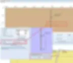
Figure 3.18.4: Edit wall out-of-plane position and rotation from vertical
In DeepEX additional wall elements can be defined on the two main walls (Left and Right main wall – see section 3.17). These wall elements can be used either to change the wall section in depth (i.e. in case of sheet pile placed on concrete piers), or to design both temporary and inner permanent walls of an excavation project.
Drawing a wall element
The tool to draw an additional wall element on left or right main wall can be accessed from the General tab of DeepEX, by pressing the small arrow next to Edit 1st Wall or Edit 2nd Wall respectively (Figure 3.19.1). Next, we have to click on the model area on two spots, close to the point the new wall element needs to be installed (below or next to the main wall).

Figure 3.19.1: Options to draw additional wall elements on each main wall

Figure 3.19.2: Procedure to add a wall element on the right side of the left main wall
Defining Additional Wall Element Position and Properties
The Edit Wall Data dialog appears as soon as the wall is inserted. The same dialog appears when we double-click on any additional wall element in the model area. In this dialog we can define the name, structural section (choosing from the project wall sections database), dimensions (top and bottom wall element elevation) and position of the new wall element (options to place the new wall element along the main wall axis or next to the wall, right beside or in a certain offset distance).
Note: As wall element section can be assigned any of the wall sections existing in the project database (see section 3.7). |

Figure 3.19.3: Define new wall element name, structural section and position
In the Advanced Features tab, we can define the wall element behavior (master wall – slave to the main wall) and the top and bottom releases (used in Non-Linear analysis only).

Figure 3.19.4: Additional wall element advanced features
Use of the Additional Wall Elements
The additional wall elements tool can be used to simulate one of the following scenarios:
A. Use as internal permanent wall, next to a main temporary wall used only for the support of the excavation. In this case, we need to select the additional wall element tool and click on 2 spots next to the wall. In the dialog that appears we can select the start and end elevation of the new wall element, as well as if we wish to place it on the left or right side of the main wall.

Figure 3.19.5: Additional wall element next to a main wall
B. Use to change the wall section along the wall depth (i.e. simulate concrete piles below sheet piles, soldier piles over secant piles etc). In this case, we have to click on two spots over or under the main wall, and in the dialog that appears we have to select to position the new wall element along the main wall axis.

Figure 3.19.6: Additional wall element along a main wall
In each construction stage we can perform excavations, dewatering and backfill operations independently. These operations can be done with the tools in DeepEX General tab and toolbar, or graphically on the model area.
Defining Exact Ground Surface and Water Elevations
In the General tab of DeepEX we can define the exact elevation of ground surface and water table for each wall side, in each construction stage. By changing the values in the boxes we can set the elevation in the specific stage, performing excavations, dewatering and backfill operations in comparison with the previous stage.

Figure 3.20.1: Additional wall element advanced features
By accessing the Ground Water Options table, we can define the exact water elevation on each wall side and choose to dewater automatically (option maintain at subgrade).

Figure 3.20.2: Ground water table options
Excavating, Backfilling and Dewatering Graphically
In the interactive model area of DeepEX we can move the mouse over any ground surface or water line and drag-and-drop it, performing excavations, backfill or dewatering operations graphically.

Figure 3.20.3: Drag and drop aground surface in the model area
Backfilling and Excavating with the Backfill Operation and Excavation tool
From the toolbar on the left side of DeepEX main screen, right above the “Check model” option, we can access the backfill and excavation tools. By accessing any of them, we can click on various points on the model area (from left to right), and after the last click press the “Enter” button from the keyboard. DeepEX will create the new ground surface, using the inserted points.

Figure 3.20.4: Backfill with the backfill operation tool
As mentioned in section 2.3, deep excavations always require staged construction, since even the wall construction can affect the performance. In each design section in DeepEX we can add and modify independently unlimited number of construction stages.
Our general recommendation: In DeepEX, we should always start from an initial stage with at-rest conditions (no excavation), and then start adding design stages and perform design steps, trying to simulate the construction procedure (perform excavation up to the first support level, install support level, perform a further excavation or a backfill operation etc.). Additional stages can be added after the final stage, and these can be used to check different soil pressure methods, seismic conditions and more. |
Adding Construction Stages and Editing the Stage Name
A new construction stage can be added either by right-clicking on the last stage and pressing “Add stage”, or by pressing the “Add stage” option in the General tab of DeepEX. Either way a new construction stage will be added in the Stages area right below the model. The new stage will be an exact copy of the last created stage.
We can right-click on each stage and select the option “Edit Name”. The name can be typed in the command line of DeepEX.

Figure 3.21.1: Options to add construction stages

Figure 3.21.2: Option to edit the name of a construction stage
Deleting a Construction Stage
A construction stage can be deleted either by right-clicking on the specific stage and pressing “Delete stage”, or by selecting a stage and pressing the “Delete stage” option in the General tab of DeepEX. In all cases, the selected stage will be deleted from the design section’s stages list. Along with the construction stage, there will be deleted all ground surface and water modifications in the specific stage.

Figure 3.21.3: Options to delete a construction stage
Inserting a Construction Stage
A construction stage can be inserted right before a selected stage. The new stage will be an exact copy of the selected stage and it can be modified independently. A stage can be inserted either by right-clicking on the specific stage and pressing “Insert stage”, or by selecting a stage and pressing the “Insert stage” option in the General tab of DeepEX.

Figure 3.21.4: Options to insert a construction stage
In DeepEX we can use several support types to simulate any deep excavation system. Figure 3.22.1 presents the available support types. The supports can be added in any construction stage. There is also an option to remove a support from a certain construction stage and after.

Figure 3.22.1: Available support types in DeepEX
Adding Supports
Supports can be added in the model area graphically. We can use the Draw Supports toolbar in the General tab of DeepEX, select the support type and click on the model area to add the support. For tiebacks and rakers, we first have to click on the wall and next to the ground. For struts, concrete slabs and tierods connecting opposite walls, we have to click first on the left and next on the right wall. For springs, waler and fixed supports, we have to click one time on the wall.

Figure 3.22.2: Draw supports tools in DeepEX
After drawing the support on the model area, the Edit Supports dialog appears. The same dialog can be accessed any time, by double-clicking on a support in the model area. This dialog is customized based on the selected support type. In all cases, we have to define the exact support elevation on the wall and the support spacing (support row on the deep of the screen).
In case of tieback supports (ground anchors), we have to define additionally the lengths of the free and bonded part of the tieback and the installation angle. The tieback structural section can be selected from the project database. This database can be edited and new tieback sections can be added and modified (see section 3.8). Finally, we have the option to use helical anchors instead of normal tiebacks. In that case, the helical anchor database can be accessed and modified (see section 3.11). The ground anchor tool can be used also to define a tierod, connecting the opposite walls horizontally.

Figure 3.22.3: Add and edit a tieback support in the model area
In case of spring supports, we can choose to use elastoplastic springs and in that case define the spring stiffness parameters.

Figure 3.22.4: Add and edit a spring support in the model area
In case of steel struts, we can define additionally the unbraced lengths (vertical and horizontal), in case these are limited. The strut structural section can be selected from the project database. This database can be edited and new strut sections can be added and modified (see section 9). Finally, we have the option to use mechanical or hydraulic strut sections instead of normal struts. In that case, the mechanical and hydraulic strut sections database can be accessed and modified (see section 3.10).

Figure 3.22.5: Add and edit a strut support in the model area
In case of steel rakers, we can define additionally the installation angle. The raker structural section can be selected from the project database. This database can be edited and new raker sections can be added and modified (see section 3.9). Finally, we have the option to use mechanical or hydraulic raker sections instead of normal rakers. In that case, the mechanical and hydraulic strut sections database can be accessed and modified (see section 3.10).

Figure 3.22.6: Add and edit a raker support in the model area
In case of reinforced concrete slabs, we can define additionally the unbraced lengths (vertical and horizontal), in case these are limited and the slab live load. The slab structural section can be selected from the project database. This database can be edited and new slab sections can be added and modified (see section 3.12).

Figure 3.22.7: Add and edit a slab support in the model area
In case of waler supports, we can define additionally the unbraced lengths (vertical and horizontal), in case these are limited. The waler structural section can be selected from the project database. This database can be edited and new strut sections can be added and modified (see section 3.14).

Figure 3.22.8: Add and edit a waler support in the model area
Deleting a Support
A support can be deleted from the model area by taking the mouse over a specific support until it highlights and press the “Delete” button from the keyboard. This action will permanently delete the selected support from all stages.

Figure 3.22.9: Delete a tieback support from the model area
Removing/Deactivating a Support
In some cases, we need to use a support and remove it in a later construction stage. A support can be deactivated from the model area by right-clicking on the support and selecting the option “Deactivate”. This action will deactivate the support for the specific construction stage. The support will be active in following stages, if the stages were created before the deactivation. To deactivate in all following stages, we have either to do it manually in each stage (access a stage, right-click on the support and select deactivate), or use the option “From this stage and then “Deactivate”.

Figure 3.22.10: Options to deactivate a support
In DeepEX we can select to apply a wale beam on an existing support graphically. The Draw wale beam tool can be accessed from the Draw Supports toolbar, in the general tab of DeepEX. We have to select the tool and then click on the support, close to the wall where the wale beam needs to be installed. In the dialog that appears (Figure 3.23.1), we can select or edit the wale beam section (see section 3.13), the spacing and the loading type (Point Loads - Figure 3.23.2 and Distributed Loads – Figure 3.23.3).
Note: The installation of a wale beam does not affect the wall and support results in DeepEX. The software will use the defined wale beam loading pattern to design and calculate stress checks on the wale beam. In 3D models the wale beams are generated automatically by the software, even if they were not used on the 2D model by the user (3D Frame Analysis additional optional module is required for this option). |

Figure 3.23.1: Add and edit a wale beam on an existing support

Figure 3.23.2: Wale beams point load types

Figure 3.23.3: Wale beams uniform load types
Concrete heelblocks are used as passive elements that transfer raker forces to soil. In DeepEX a heelblock can be connected to one or more rakers at the same time. DeepEX considers the net horizontal force balance on the heelblock. For calculating the safety factor against sliding, DeepEX calculates the active and passive earth forces on each heelblock side. Passive and active earth forces are computed using an average surface angle according to Coulomb theory with no wall friction. Wall friction is ignored for heelblocks since the increased passive resistance can only be realized at considerably greater displacements. DeepEX does not consider the bearing capacity of a heelblock in the vertical direction.
The Draw a passive heelblock tool can be accessed from the Draw Supports toolbar, in the general tab of DeepEX. We have to select the tool and then click on the support, close to the poin that the support is connected to the soil. In the dialog that appears, we have to define heelblock exact position (x-coordinate and elevation), size, shape and materials.
After a heelblock is installed, we can double-click on each support and select the option to “connect base to heelblock”.

Figure 3.24.1: Add and edit a passive heelblock
On the model area of DeepEX we can define several external loads, simulating traffic loads, construction loads, train loads, loads from nearby building foundations and more, that could be acting on our support system. Figure 3.25.1 presents the load types that can be used in DeepEX.
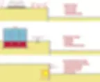
Figure 3.25.1: External load types in DeepEX
Adding and Editing a 2D External Load
Loads can be added in the model area graphically. We can use the Draw Loads toolbar in the General tab of DeepEX, select the load type and click on the model area to add the external load. For surface strip surcharges, we have to click on two points on the ground (from left to right). For surface point loads and train loads we have to click on a single point on the ground surface. For loads on the wall, we need to click on one or two points on the wall, depending on the load type.

Figure 3.25.2: Draw loads tools in DeepEX
After drawing the load on the model area, the Edit Loads dialog appears. The same dialog can be accessed any time, by double-clicking on a load in the model area. This dialog is customized based on the selected load type. In all cases, we have to define the exact load location (on the ground surface – X coordinates and on the wall – Z Coordinates), and the load magnitude.
NOTES: In DeepEX, we can access the loads in different stages (double-click on the load) and define a different magnitude). The loading type option (permanent or variable) will be used only when a design standard will be applied. In that case, the load will receive a partial factor according to the selected standard. In case of surface strip surcharges or point loads, we have to select the tool from the Draw Loads toolbar and click on two (from left to right) or one point on the surface area respectively. In the dialog that appears we can define the exact load position (X coordinates) and the load magnitude qz. If the load should be placed below the ground surface to simulate any underground load, then we should unselect the option “Is Surface” and define the load elevation. |

Figure 3.25.3: Add and edit a surface strip surcharge
In case of strip surcharges or point loads on the wall (load, moment, prescribed displacement), we have to select the tool from the Draw Loads toolbar and click on two (from top to bottom) or one point on the wall respectively. In the dialog that appears we can define the exact load elevation on the wall (Z coordinates) and the load magnitude qx.

Figure 3.25.4: Add and edit a strip surcharge on the wall
On the model area of DeepEX we can add 3D loads, using the tools from the Draw Loads options toolbar in the General tab.
In case of 3D buildings, we have to select the tool click on the desired point on the ground surface, where the building needs to be installed. In the Basic tab of the Building Wizard, we can define the basic building parameters (exact building position (X0 and Y0 coordinates), the building surface dimensions (widths along X and Y axis), the total number of building superstructure and basement floors and the number of columns per axis).

Figure 3.6.1: Add a building and edit the basic building properties
In the Floors tab, we can define the thickness, material, live and dead loads of each building floor (superstructure typical floor, basement typical floor and floor beam).

Figure 3.26.2: Edit the building floor dimensions and loads
All loads in DeepEX are eventually transferred to rectangular footings. While not every footing in the real world is rectangular, this simplification captures most cases. The Footings tab gives the option to define the footing dimensions.
NOTE: DeepEX assumes that all footings are made of concrete and calculates the dead load of each footing based on its dimension. Also, DeepEX gives the option to include grade beams that connect all building footings. |

Figure 3.26.3: Edit the building footing dimensions
Floor loads are eventually transferred to footings with the help of building columns. Column shape, dimensions and materials can be defined in the Columns tab.

Figure 3.26.4: Edit the building column properties
Most buildings have walls. In order to better simulate building loads, DeepEX gives you the option to simulate different exterior, interior and basement walls. Wall loads are calculated from the wall area times the density. The open wall space can be used to simulate doors, windows, and other openings that do not have any dead load.

Figure 3.26.5: Edit the building wall properties
In the Advanced tab, we can select the option to include relief load calculations. By checking this option, DeepEX removes the effect of soil’s dead load on the surcharge stresses since this soil is removed in order to create the basement. This is done with elastic solutions by averaging the vertical stresses on all building corners.

Figure 3.26.6: Option to include relief load calculations
Building footings can be edited by right clicking on them from the plan view. If a footing is moved or its dimensions are changed, then the building loads will be changed (if the user decides to do so). All column loads are calculated based on approximate tributary areas from each supported floor. At the same time, the building will be saved is a long format since it is not fully rectangular.

Figure 3.26.7: Option to edit each building footing on the pan view area.
In case of 3D Footings, we have to select the tool click on the desired point on the ground surface, where the footing needs to be installed. In the Edit Footing dialog that appears (same in Figure 3.26.7 above), we can define the exact footing position, dimensions and the load on the footing head.
The construction stage in which we choose to draw an external load is important in DeepEX. The load is activated from the installation stage and after. In all previous stages the load appears light-grey (deactivated).

Figure 3.27.1: 20ft Excavation with rakers – load activated from stage 2
In case we need to activate or deactivate the load in any stage, we can right-click on it and select the option “Activate” or “Deactivate” respectively.

Figure 3.27.2: Deactivating a load
The Elastic load options dialog can be accessed from the Draw load toolbar in the General tab of DeepEX (Figure 3.28.1). In this dialog we can define the surcharge modeling method. Figure 3.28.2 presents the methods implemented in DeepEX.

Figure 3.28.1: Open elastic load options and select a method

Figure 3.28.2: Load pressures methods in DeepEX

Advanced Video Examples
New videos, covering several deep excavation design cases and DeepEX capabilities!
New Examples with DeepEX - Shoring Design Software

Projects designed with DeepEX
$2 Billion Hudson Yards, New York | Circular wet soil mix shaft, Florida | Soldier Pile Wall in Manhattan, NY |
 |  |  |

DeepEx Demo
Structural and Geotechnical design of Deep Excavations.
Try the Full version for free and see how you can design and optimize any deep excavation model in the most efficient way!

Web Presentation
Get a Free online presentation! Learn about all software features and capabilities!

Purchase DeepEX
Get the most powerful shoring design software! Customize your version!

Software
Review our software programs for geotechnical engineers and contractors!
Trusted by

