Section 10: Gravity Walls and Pile Supported Abutments
- Nour Ben Mabrouk
- Feb 14, 2024
- 5 min read
Updated: May 20, 2025
SECTION 10: OPTIONAL MODULES: GRAVITY WALLS AND PILE SUPPORTED ABUTMENTS
DeepEX offers the possibility to design gravity retaining walls and pile supported abutments. These options are available through the Gravity Walls and the Pile Supported Abutments modules respectively. The modules can work in DeepEX either together, or independently. In both modules we have to define the structural section through the same “Retaining Wall Data” dialog. In case that only one of the modules is activated, then the software can either analyze gravity walls, or pile supported abutments, depending on the activated module.
This section presents the use of these modules and the analysis results when a gravity wall or a pile supported abutment is analyzed.
With the Gravity Walls module of DeepEX, we have the flexibility to create basic types of retaining walls such as full gravity or with stem. Flexural, reinforcement can be included where ever desired. Keep in mind that a gravity wall can also be used as a pier or an abutment wall with piles.
The use of gravity wall in the model can be defined in the “Edit wall data” dialog of DeepEX, which appears when we double-click on the wall on the model area. When the Gravity wall module is activated, there appears the option “Use gravity wall section”.

Figure 10.1.1: Edit wall data dialog – Use gravity wall section option
When the “Use gravity wall” option is selected, we can press on the button “Edit section data”. This will cause the “Retaining wall data” dialog to appear (Figure 10.1.2). There we can define the retaining wall dimensions and reinforcement.

Figure 10.1.2: Define retaining wall section type, dimensions and reinforcement
The following retaining wall types are available in DeepEX:

Figure 10.1.3: Retaining wall types in DeepEX
Calculate Driving Pressures from edge of wall option
In the default mode, stability safety factors are calculated from soil and other pressures directly acting on the driving wall sides. While this assumption gives very good, approximate results, in theory the driving horizontal pressures can be taken at the wall edge. By selecting this option, safety factors are calculated by pressures acting directly on a vertical wall edge that is defined from the left most base coordinate if pressures are driving from left to right or the right most coordinate if pressures are driving from right to left. If this option is selected, then driving soil pressures on this vertical edge are always taken as Active or At-rest.
The reinforcement data table enables the use of reinforcing bars on each wall face. The wall sides numbering starts from point A, which is always the bottom left point of the section and continues clockwise.

Figure 10.1.4: Retaining wall data – Reinforcement table
NOTE: DeepEX does not account for development lengths and reinforcement bending. It is the final responsibility of the engineer to decide how reinforcement has to be bent, cut, or shaped for fabrication. DeepEX though will calculate and report all bending and shear capacities. |
After the analysis is succeeded, we can double-click on the wall in the model area and access the retaining wall data dialog. There, in the Results tab, we can review the retaining wall results for sliding, overturning and bearing conditions.
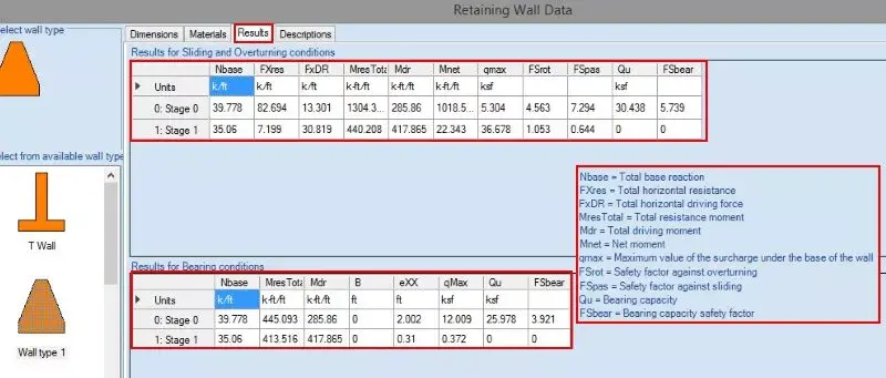
Figure 10.2.1: Retaining wall results
Graphical results can be obtained on the model area, after the analysis is succeeded. We can review all wall diagrams (moments, shear stresses, axial forces, displacements) and the soil and water pressures acting on the gravity wall.

Figure 10.2.2: Retaining wall graphical results – Wall moment diagram
When the Pile supported abutments additional, optional module is activated (either standalone, or with the Gravity Walls module activated), we can create retaining walls and define the supporting piles sections and position. The use of a pile supported abutment in the model can be defined in the “Edit wall data” dialog of DeepEX, which appears when we double-click on the wall on the model area. When the Pile supported abutments module is activated, there appears the option “Use gravity wall section”.

Figure 10.3.1: Edit wall data dialog – Use gravity wall section option (pile abutments)
In the Retaining Wall Data dialog, we have to choose to use Pile Supported Abutment.

Figure 10.3.2: Option to analyze a pile supported abutment
NOTE: To run gravity walls and pile supported abutments, the possession of both modules – Gravity walls module and Pile supported abutments module) is necessary. If only one of the modules is purchased and activated, then DeepEX can analyze only the respected wall type. |
Defining Abutment Section and Reinforcement
The wall structural section can be defined as a gravity wall (see section 10.1), by defining the section shape, dimensions and reinforcement.

Figure 10.3.3: Define the abutment section shape and dimensions
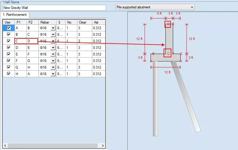
Figure 10.3.4: Define the abutment section reinforcement
Defining Foundation Piles Positions and Structural Sections
We have to access the “Pile (Abutments)” tab. In this tab, we can select to add piles, define the pile position (X and Y coordinates) and select to edit the pile structural section. Also, there is an option that the pile head is fixed in pile cap.

Figure 10.3.5: Add piles and define pile positions
By pressing the button “Edit” next to each pile, we can define the pile type and the pile section. In the “Edit Pile Dimensions and Data” dialog that appears (see Figure 10.3.6), user can define the following options:
Pile Type (Helical or Non-Helical pile)
Free length (where adhesion or side resistance is ignored).
Installation angle (90 deg = vertical pile)
Installation method (option available for non-helical piles only). The following options are available:
Drilled piles
Driven piles
Caisson piles
Micropiles
CFA (Continuous Flight Auger) piles
Drilled-In-Displacement piles
Structural section and pile length. User can define the depth of each pile segment and select a structural section. The structural sections list can be updated by pressing the “Edit” button next to each pile section segment.
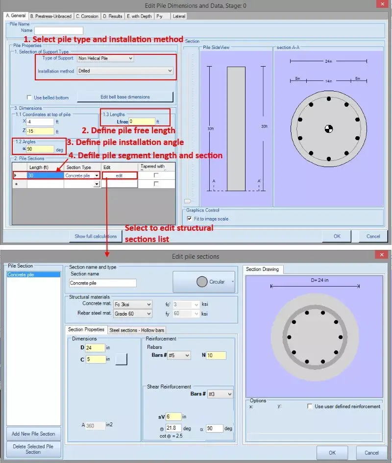
Figure 10.3.6: Define pile type and structural section
Data entry: Helical Pile Sections
From the Helical Anchors dialog we can select an anchor from the existing database of anchors or add some sections to the database. These anchors can be used in the project. The General tab contains basic structural information. The Geotechnical capacity tab contains options for calculating the geotechnical tieback capacity. For more information about the helical anchors dialog, please see section 3.11.
Data entry: Non-Helical Pile Sections
From the Pile Sections dialog we can create a list with pile sections that we can use along the pile. We can add several pile sections to the list on the left side of the dialog, access each added section and edit them independently, by defining the pile section type, dimensions and reinforcement.

Figure 10.3.7: Edit non-helical pile sections
For reinforced concrete sections, user can define the rebar size and number of bars. For steel sections (pipes, H piles), user can select the steel section from the software implemented databases.
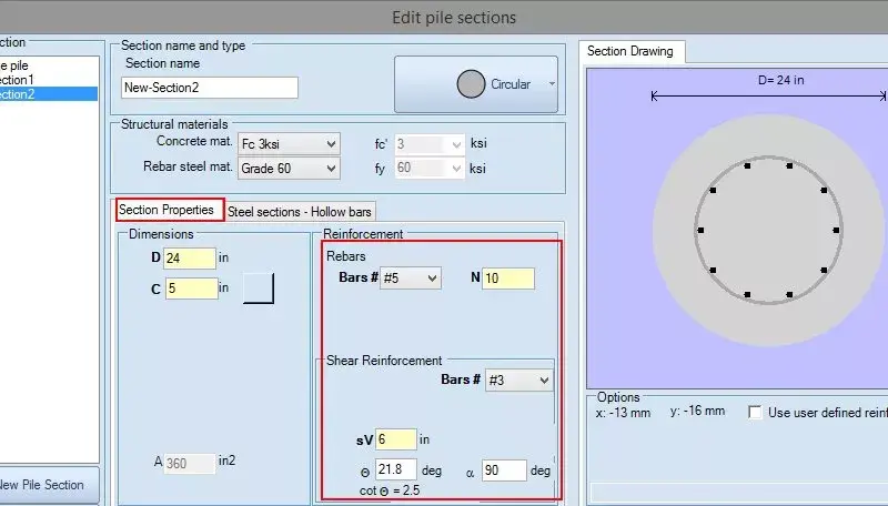
Figure 10.3.8: Edit reinforced concrete section reinforcement

Figure 10.3.9: Edit steel section reinforcement
After the analysis is succeeded, we can double-click on the wall in the model area and access the retaining wall data dialog. There, in the Results tab, we can review the retaining wall results for sliding, overturning and bearing conditions (same as Gravity walls – review section 10.2, Figure 10.2.1).
Graphical results can be obtained on the model area, after the analysis is succeeded. We can review all wall diagrams (moments, shear stresses, axial forces, displacements), the soil and water pressures acting on the abutment, as well as the pile results (pile moment, shear, axial and displacement diagrams, bearing capacity results).
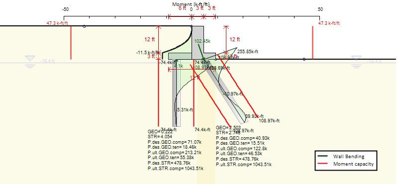
Figure 10.4.1: Graphical results – Pile moment diagram and bearing capacity results
Advanced Video Examples
New videos, covering several deep excavation design cases and DeepEX capabilities!
New Examples with DeepEX - Shoring Design Software

Projects designed with DeepEX
DeepEx Demo
Structural and Geotechnical design of Deep Excavations.
Try the Full version for free and see how you can design and optimize any deep excavation model in the most efficient way!
Web Presentation
Get a Free online presentation! Learn about all software features and capabilities!
Purchase DeepEX
Get the most powerful shoring design software! Customize your version!
Software
Review our software programs for geotechnical engineers and contractors!
Trusted by


