
Section 2: DeepEX Interface Features
- Feb 12, 2024
- 7 min read
Updated: May 20, 2025
SECTION 2: DEEPEX INTERFACE FEATURES
The real beauty of DeepEX, is the unique interface that allows us to quickly and easily access and edit all object items and methods, assisting in the rapid discovery of the most efficient model for any deep excavation project.
This section includes information about the DeepEX interactive interface and the provided options to access and edit several items on the model area (toolbars, tree view options, boring locations). In addition, we provide information about the use and significance of design sections and construction stages in DeepEX. We describe how to define the unit system in a project file and how to access the software extensive international databases of steel sections (H Beams, pipes, channels, rectangular hollow sections and sheet piles). Finally, we briefly present the analysis methods that can be used in DeepEX.
DeepEX offers a user-friendly, interactive interface. We can easily create several design sections and construction stages, access the interactive model area to edit fast all items and create the model graphically and select to run the analysis. The main interface is shown in Figure 2.1.1.

Figure 2.1.1: General DeepEX interface
In DeepEX we can work with many design sections of an excavation. In a sense, a design section is a design scenario. Each design section can be independent or can be linked to a parent model. This way, multiple conditions can be examined simultaneously.
We can use the design sections in order to simulate different excavation locations and walls. Each design section can open in a different tab above the model area. We can access these tabs and modify independently the soil properties and stratigraphy, the wall sections, the support types, the construction stages, the surface and water elevation in each stage, the analysis options etc. Figure 2.2.1 presents how the design sections can be accessed from tabs.

Figure 2.2.1: DeepEX design section tabs
By right-clicking on the design sections area, we can select to rename, add or delete design sections. When we press to “Add Section”, an independent blank section with no construction stages is added. When we press to “Add as a new section”, an independent copy of the design section you have currently selected (right-clicked on) is added. This new design section includes all the construction stages, supports and surface /water elevations of the original section, and we can later modify it independently.

Figure 2.2.2: Manage design sections list
When we press to “Add new linked section”, a linked copy of the design section you have currently selected (right-clicked on) is added. This new design section includes all the construction stages, supports and surface /water elevations of the “parent” section. Any model modification to one of the linked sections, will pass to all of them automatically. The only “unlinked” options in this case are the analysis method and the different analysis options (design codes, soil pressure methods etc.). The linked sections option can be used so we can assign and run different analysis cases on the same model fast and compare the results.
Even independent design sections can be linked and unlinked any time from the Analysis tab of DeepEX. By pressing the “Link option” button, we can choose to link the selected design section to any other. There we can find the option to link or not link the analysis type.

Figure 2.2.3: Link design section options in DeepEX
The design sections list can also be managed by the Edit Design Sections toolbar, as presented in section 2.8.
Deep excavations always require staged construction, since even the wall construction can affect the performance.
Our general recommendation: In DeepEX, we should always start from an initial stage with at-rest conditions (no excavation), and then start adding design stages and perform design steps, trying to simulate the construction procedure (perform excavation up to the first support level, install support level, perform a further excavation or a backfill operation etc.). Additional stages can be added after the final stage, and these can be used to check different soil pressure methods, seismic conditions and more. |
When we select to add a stage in DeepEX, a new stage is added as an exact copy of the last stage. This new stage can be modified independently. There are options to rename, delete or insert a stage right before of a selected one. We can add, delete or insert stages either from the options in the General tab, or by right-clicking on a stage right below the model area.
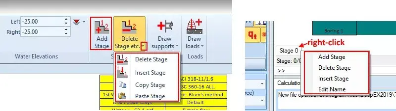
Figure 2.3.1: Manage stages in general tab and below the model area
DeepEX will run the analysis and present the results of each construction stage in tables and graphically on the model area. This way, we can identify the most critical stage, which is not always the last one. All structural items will be designed from the most critical stage results. The recognition of the most critical stage allows us to decide to take actions (edit support locations, structural sections etc.) to achieve the most efficient model optimization. Figure 2.3.2 presents a staged excavation in DeepEX.

Figure 2.3.2: Staged excavation in DeepEX
DeepEX software includes the classical Limit Equilibrium method (LEM), a Non-Linear analysis method (NL) where the software uses elastoplastic Winkler springs, and the 2D Finite Element Analysis method (FEM – available as an additional optional module). Figure 2.4.1 presents the analysis methods as presented in the Analysis tab of DeepEX.
The combination methods (LEM+NL and LEM+FEM) can be also selected. In this case, the software will use the limit equilibrium method to calculate the wall embedment FS, and then will perform the non-linear or finite element analysis to calculate all other results.

Figure 2.4.1: Analysis options
The selection of an analysis method is an important decision. In general, LEM method is the classical method accepted by any authority, and it is a quite easy method to verify. On the other hand, it ignores the soil-structure interaction and all stages are independent. The wall deflections are estimated independently for each stage, something that might lead to unrealistic results, especially in cases of excavations with many support levels. The advanced methods like NL or FEM might lead to very realistic results, but we have to be careful during the definition of the soil properties.
Our general recommendation is our users to perform all types of analysis and finally design the project for the most critical. |
Our general recommendation is our users to perform all types of analysis and finally design the project for the most critical.
You can find more detailed information about the analysis methods is section 4.1.
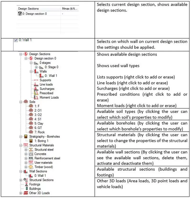
DeepEX offers features that include multiple design sections and a tree-style project view. The tree view enables the user to quickly access vital project data, as well as visualize crucial project settings. The next table briefly describes the functionality of the Wall list, Design Section List, and Tree View items.
Table 2.5.1: DeepEX Tree view items
DeepEX incorporates different design systems that can easily be selected from a drop-down on the bottom left side of the screen, right below the design sections list area. We can select among English units, SI units and more. The unit change can happen any time. All item sizes and magnitudes are adjusted to the new unit systems and the values are accurately converted.

Figure 2.6.1: Select a unit system in DeepEX
DeepEX implements extensive international databases of steel sections (H beams, Channels, Pipes, Rectangular Hollow, Sheets etc.) and rebar sizes. We can easily load the databases used in the local area, by selecting the option from the Design tab (Figure 2.7.1). Later, when choosing any steel section or rebar size from the software database to apply to a wall or support section, all the section properties are loaded automatically.

Figure 2.7.1: Select a steel sections/rebars database
DeepEX software includes a number of toolbars, allowing us to quickly perform several actions on the model area. The following section provides a detailed list of all toolbar functions.
Start button, located on the top left side of the main screen, allows us to create a new project, access and open saved projects, save the current project and more. Figure 2.8.1 presents the start button toolbar options.
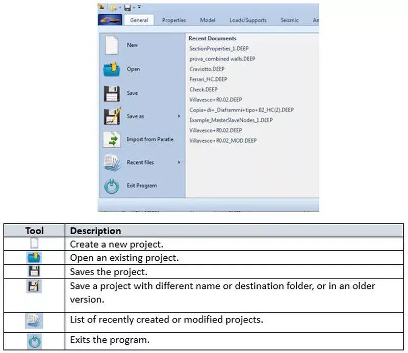
Figure 2.8.1: Start button toolbar options
An Edit View-Draw toolbox is available on the left screen side under the design sections list. The available tools are described in the table below:

Figure 2.8.2: Edit View-Draw toolbar options
On the top left side of the main screen, right under the design section list appears the Edit Design Sections toolbar that helps us manage the design sections list. The icons are presented and described in the table below:
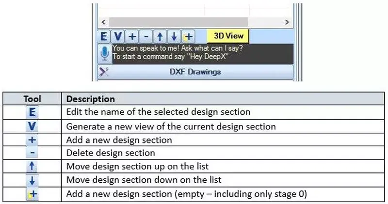
Figure 2.8.3: Edit design sections toolbar options
The Calculations toolbar is located in the bottom right side of the screen and allows us to either calculate the selected design section, or to calculate all the design sections that are included in the Design Sections list at the same time.
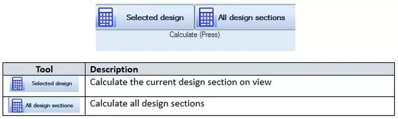
Figure 2.8.4: Calculations toolbar options
In the Edit View-Draw toolbar (see section 2.8), we can locate an option to define the boring position in the model area. Figure 2.9.1 presents the available options:

Figure 2.9.1: Define boring position in the model area options
NOTE: The boring location selection is important, because it affects the view on the model area, as well as the appearance of the screenshots in printed reports and the exported sketches (Export to DXF additional optional module). |
The option Exact x places the boring location on the exact x-coordinate defined in the Edit Boring dialog (Figure 2.9.2).
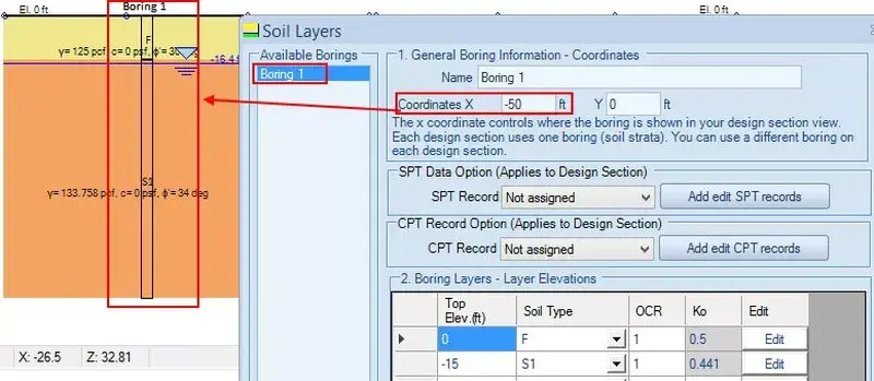
Figure 2.9.2: Exact X boring location in model area
The option Side view table, places the boring information on the left side of the model itself.
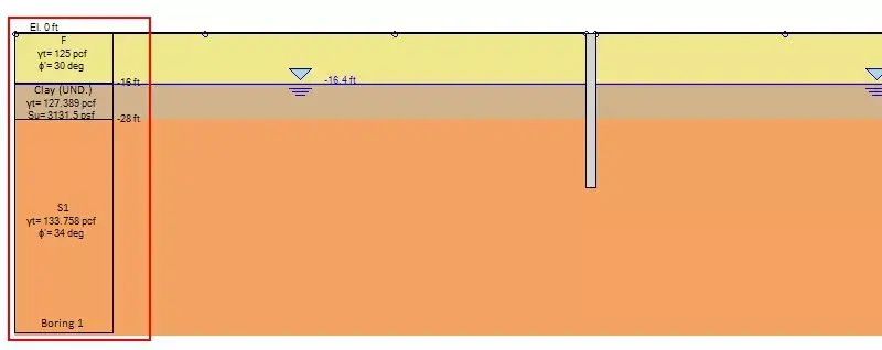
Figure 2.9.3: Side view boring location in model area
The option Side and Table creates an additional table with Soil Layers information. The position of the table in the model area can be later defined in the View tab of DeepEX.
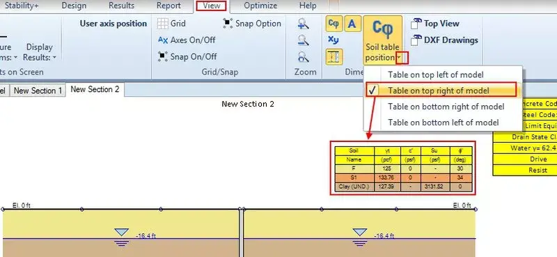
Figure 2.9.4: Side and Table boring location in model area
In order to change the software default settings, we have to start the software as administrator, open the Settings dialog from the Help tab and press to set the current project as default.
IMPORTANT: Changing the default software parameters is an important procedure and we have to be very careful. By setting a project as default, we actually select the project that will be loaded each time we open the software. It is highly recommended that any settings changes should be applied in a clear model with no modifications to soil properties, stratigraphies, construction stages etc., else these settings will be saved as default as well. |
The following procedure should be followed:
A. With the software closed, we should take the mouse over the software icon in the PC Desktop and RIGHT-CLICK on it.
B. From the menu that appears, we have to select to run the software as administrator.

Figure 2.10.1: Option to open DeepEX as administrator
C. In the Help tab of DeepEX, we can select the option Settings. In the dialog that appears, we can define all initial software settings (unit system, language, company and engineer name, font sizes, structural codes and more). We can also change the company logo, which appears in the DeepEX reports. The logo should be in jpg format, with dimensions 300x52 pixels. After changing all parameters, we can select to set the project as default.

Figure 2.10.2: Change settings and set project as default

Advanced Video Examples
New videos, covering several deep excavation design cases and DeepEX capabilities!
New Examples with DeepEX - Shoring Design Software

Projects designed with DeepEX
$2 Billion Hudson Yards, New York | Circular wet soil mix shaft, Florida | Soldier Pile Wall in Manhattan, NY |
 |  |  |

DeepEx Demo
Structural and Geotechnical design of Deep Excavations.
Try the Full version for free and see how you can design and optimize any deep excavation model in the most efficient way!

Web Presentation
Get a Free online presentation! Learn about all software features and capabilities!

Purchase DeepEX
Get the most powerful shoring design software! Customize your version!

Software
Review our software programs for geotechnical engineers and contractors!
Trusted by


